Final Assembly

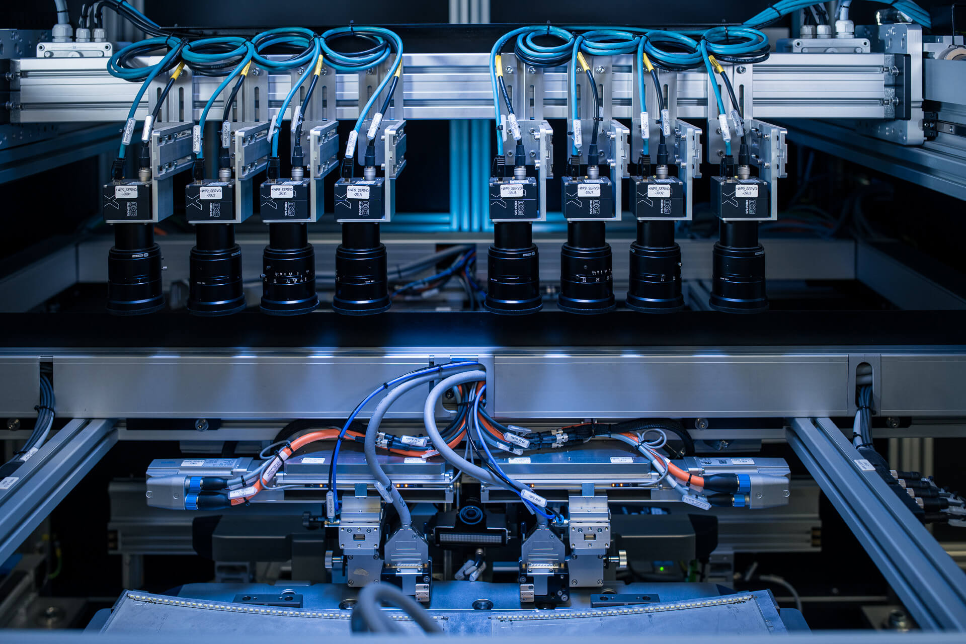
Automatic or semiautomatic lines come equipped with advanced AI vision systems for component positioning and tolerance measurement. Wherever those are impractical, digital contact sensors can perform high-accuracy measurements of thickness, flatness, and parallelism. Servo-controlled presses handle delicate press operations, guided by force sensors for even distribution.

These lines are modular by design, allowing for easy adaptability and future upgrades. They also feature energy consumption measurements for both air and electricity, providing valuable data for optimizing operational efficiency. Integrated with MES systems, the lines offer streamlined operation and quality control.

1
  • 1Display & backlight loading
  • 1.1Robot pick and place
  • 1.2Placement verification
2
  • 2Surface activation
  • 2.1Plasma treatment
3
  • 3Display assembly
  • 3.1Gap filler dispensing
  • 3.2Robot pick and place
4
  • 4PCB assembly
  • 4.1Tray feeding mechanism
  • 4.2Robot pick and place
  • 4.3Robotic screwdriving
5
  • 5Camera Assembly
  • 5.1Tray feeding mechanism
  • 5.2Robot pick and place
6
  • 6Back cover assembly
  • 6.1Tray feeding mechanism
  • 6.2Robot pick and place
  • 6.3Robotic screwdriving
7
  • 7End of line test
  • 7.1Product contacting
Add-on

Functionality test

To ensure that only good parts are passed forward, various functionality tests are performed at the end of line. All test results and measurements are reported to the information system for 100%...

Add-on

End of line calibration

At end of line the products are calibrated to ensure the highest quality. The biggest challenge for the display calibration is white point calibration. This process requires specialized hardware and software, such...

Add-on

Manual test

If required, a manual test station can be positioned at the end of line. The product is contacted and powered up with specially designed images for the operator to determine any potential...

Add-on

Protection foil placement

After detailed product testing, protection foil for display and other critical cosmetic components is placed on the product to avoid any potential damage during the transportation and final product installation. The station...

1 Display & backlight loading

1.1 Robot pick and place

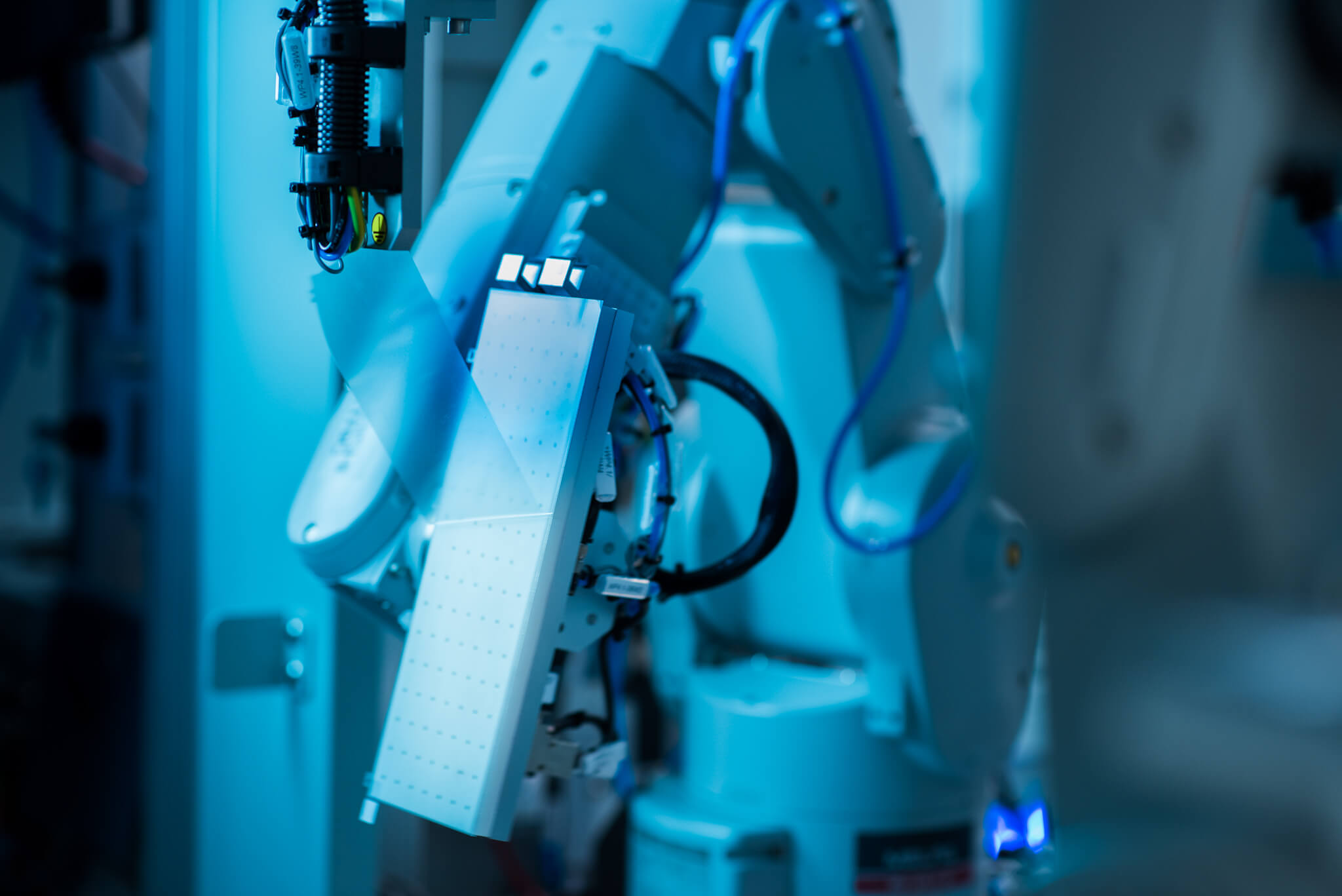
Robots are used for a repeatable precision of up to 0.01mm for placement tasks. High-level accuracy is achieved using techniques such as bush guiding combined with robot torque control, force sensors, and stroke measurements. A “stack of tolerances” analysis is conducted to ensure assembly precision. High-level accuracy is achieved using techniques such as bush guiding combined with robot torque control, force sensors, and stroke measurements. An integrated vision system is used to accurately measure part orientation and position. The components are places on special designed nests with tight tolerances to enable precise assembly.

For product manipulation, robots are equipped with grippers featuring clamping fingers or vacuum cups. Special grippers are designed that can be mounted on either pneumatic cylinders for straightforward tasks or servo motors for more intricate ones. Servo driven grippers can handle a diverse range of objects due to their programmable gripping stroke and force. Force sensors are incorporated into the grippers to allow the robot to dynamically adjust its grip, ensuring the safety of delicate components. For particularly challenging product manipulations and complex assembly tasks, additional sensors are used on the grippers.

Overall, the entire pick-and-place process is typically automated and can be programmed to repeat the same operation over and over again, with minimal human intervention. This makes it a highly efficient and reliable manufacturing method with consistent quality and accuracy.

1 Display & backlight loading

1.1 Robot pick and place

1 Display & backlight loading

1.2 Placement verification

Early detection of defective components reduces scrap, material consumption, and costs; increasing productivity. A vision system is used to verify the presence and accurately measure the position and orientation of the components, achieving a required precision of less than 0,1mm.

Measurement parameters are linked with product ID, cross-checked with nominal values, and reported to the information system. If the measured values are outside the set tolerances, the system proceeds in one of two ways:

▪ Fully Automatic Mode: The part is marked as NOK, and is not processed further. This mode requires no operator intervention.At the end of the line, the components on the carrier are unloaded, analysed, and scrapped; or sent for a rework. This mode requires no operator intervention.

▪ Manual Mode: An alarm is triggered for operator intervention. The operator then assesses whether the components are suitable for continuation. If the operator assesses the results as unsuitable, they manually remove the part and resets the system for the robot to load new components.

1 Display & backlight loading

1.2 Placement verification

2 Surface activation

2.1 Plasma treatment

Plasma treatment for aluminum-magnesium housings is an important step for surface activation. It involves cleaning, gas-based plasma generation, and controlled modification of the surface area. This treatment primes the surface for bonding by enhancing the surface adhesion properties of the housing. The specific treatment parameters depend on the desired surface characteristics and the materials involved. The parameters are fine-tuned during the design phase based on prior experience and rigorous testing.

2 Surface activation

2.1 Plasma treatment

3 Display assembly

3.1 Gap filler dispensing

An automatic gap filler system for display production is a specialized piece of equipment used to bond the cover glass (with display) with the main housing. This process eliminates the need for visible screws, leading to a sleeker and higher-quality product finish. A robot equipped with a flow control dosing valve is tasked with dispensing the exact quantity of gap filler needed. For quality assurance, a 3D scanner can then be employed to verify the contour and quantity of the dispensed gap filler.

3 Display assembly

3.1 Gap filler dispensing

3 Display assembly

3.2 Robot pick and place

A robot equipped with a specially designed gripper first detaches the gripper from its carrier and then picks up the cover glass. The robot then precisely positions the cover glass onto the housing, guided by a vision system. To ensure a tight and accurate bond between the cover glass and housing, the gripper locks onto the carrier, holding everything in place. As the gap filler begins to solidify and harden the bond, the robot releases its hold on the gripper and resets for the next part.

Meanwhile, carriers are methodically stored in a designated buffer area. This setup allows the gap filler to cure at room temperature, with the size of the buffer space precisely calculated based on the curing duration needed for the gap filler.

Overall, the entire pick-and-place process is typically automated and can be programmed to repeat the same operation over and over again, with minimal human intervention. This makes it a highly efficient and reliable manufacturing method with consistent quality and accuracy.

3 Display assembly

3.2 Robot pick and place

4 PCB assembly

4.1 Tray feeding mechanism

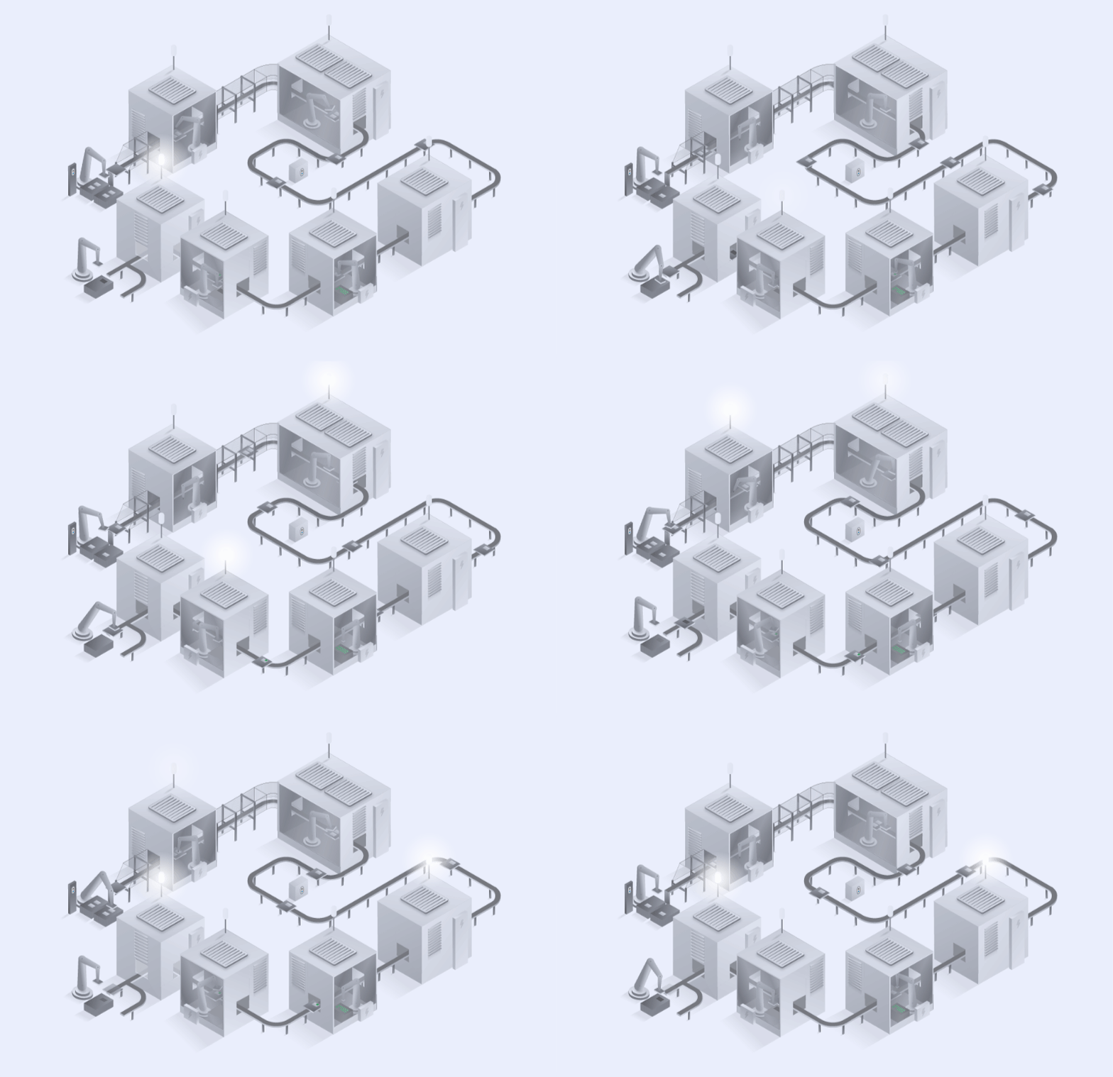
PCBAs (printed circuit board assemblies) are usually packed in trays, which are loaded into the feeder manually or by AGVs. Comprising an input conveyor, stack separator, single-track transport system, tray stacker, and output conveyor, the feeder is designed to handle trays as large as 400mm by 600mm. If room permits, the conveyors at both the input and output stages can be lengthened to enhance the assembly machine's self-sufficiency.

The core elements of the mechanism are the stack separator and the tray stacking unit. These are custom-engineered to adapt to trays of varying sizes and materials. Special-purpose servo systems with clamping mechanisms are deployed for precise tray separation. A high-precision vision system is used to identify the product's spatial orientation and position, ensuring a picking accuracy of less than 0.1 mm. When the tray's limitations prevent precise identification, an auxiliary pick-and-place system on a backlit table is needed.

Overall, the tray feeding mechanism is an efficient and reliable way to automate the feeding of various components to the assembly process, reducing the need for manual labor and improving production efficiency.
4 PCB assembly

4.1 Tray feeding mechanism

4 PCB assembly

4.2 Robot pick and place

A specialized robot is employed used for fast and reliable PCBA assembly. The camera first determines the position of the PCBA in its tray. Based on this information, the robot then accurately picks up the PCBA. Given the low tolerances of the PCBA's outer dimensions, and considering the component's sensitivity, the robot uses pneumatically actuated gripper fingers to securely lift the PCBA by its outer edges. To account for any potential discrepancies from the tight assembly tolerances, the relative position of the part to the robot gripper is checked once again – a step referred to as "gripper compensation". This feature ensures the robot's capability to precisely align the PCBA onto the housing.

Overall, the entire pick-and-place process is typically automated and can be programmed to repeat the same operation over and over again, with minimal human intervention. This makes it a highly efficient and reliable manufacturing method with consistent quality and accuracy.

4 PCB assembly

4.2 Robot pick and place

4 PCB assembly

4.3 Robotic screwdriving

A specialised robotic system is dedicated to the task of fastening the PCBA onto the housing. This robot utilizes a servo-driven screwdriver that installs screws precisely based on constantly-monitored parameters of torque, rotation angle, and screwing depth. To supply the robot with screws, either vibratory or sword feeders are implemented. Before a screw is fed into the screwdriver jaws, it passes through a screw cleaning chamber, or “particle killer”, removing any debris to maintain the product's integrity and cleanliness.

4 PCB assembly

4.3 Robotic screwdriving

5 Camera Assembly

5.1 Tray feeding mechanism

Cameras are usually packed in trays, which are loaded into the feeder manually or by AGVs. The feeding mechanism is structured with five main components: an input conveyor, a stack separator, a single-track transport system, a tray stacking mechanism, and an output conveyor. It has the capacity to accommodate trays measuring up to 400mm in width and 600mm in length. The assembly machine's operational autonomy can be increased by extending the conveyors, provided there is sufficient space.

Central to the feeding mechanism are the stack separator and tray stacker, which are specifically designed to accommodate trays of diverse dimensions and materials. To achieve accurate tray separation, specialized servo systems equipped with clamping mechanisms are used. An advanced vision system measures the product's position and orientation, achieving a picking precision finer than 0.1 mm. An additional pick-and-place system on a backlit table is required when the feeding tray's constraints do not allow for precise identification.

Overall, the tray feeding mechanism is an efficient and reliable way to automate the feeding of various components to the assembly process, reducing the need for manual labor and improving production efficiency.

5 Camera Assembly

5.1 Tray feeding mechanism

5 Camera Assembly

5.2 Robot pick and place

A robot is used for fast and reliable camera assembly. The vision system first determines the position of the camera module in its tray. Based on this information, the robot then accurately picks it up. The robot uses pneumatically actuated gripper fingers to securely lift the camera module by its outer edges. To account for any potential discrepancies from the tight assembly tolerances, the relative position of the part to the robot gripper is checked once again – a step referred to as "gripper compensation". This feature ensures the robot's capability to precisely align the part into the housing.

Overall, the entire pick-and-place process is typically automated and can be programmed to repeat the same operation over and over again, with minimal human intervention. This makes it a highly efficient and reliable manufacturing method with consistent quality and accuracy.

5 Camera Assembly

5.2 Robot pick and place

6 Back cover assembly

6.1 Tray feeding mechanism

Back covers, due to their sensitive cosmetic components, are packed into specially designed trays. To accommodate such packaging, the feeder is made of an input conveyor, stack separator, single-track transport system, tray stacking mechanism, and output conveyor. The system is specifically designed to accommodate trays with dimensions up to 400mm in width and 600mm in length. To enhance the machine's operational autonomy, the conveyors at both the entry and exit points can be extended, provided that space constraints permit.

The mechanism's critical components are the stack separator and tray stacker, which are custom-built to be adaptable to trays of varying dimensions and material compositions. To facilitate accurate tray separation, servo systems equipped with purpose-built clamping mechanisms are used. A state-of-the-art vision system is deployed to pinpoint the product's spatial orientation and position, achieving a picking accuracy of under 0.1 mm. If the feeding tray's limitations do not allow for precise enough measuremebt, an additional pick-and-place system is used on a backlit table to improve visibility.
Overall, the tray feeding mechanism is an efficient and reliable way to automate the feeding of various components to the assembly process, reducing the need for manual labor and improving production efficiency.

6 Back cover assembly

6.1 Tray feeding mechanism

6 Back cover assembly

6.2 Robot pick and place

A specialized robot gripper is designed for the careful manipulation and assembly of back covers, given their large size and sensitive cosmetic nature. Initially, the vision system, typically a combination of backlighting and imaging, detects the position of the back cover in its tray. This is challenging due to the low color contrast between the covers and their trays. Once identified, the robot accurately picks up the back cover, using grippers designed with soft foam materials and non-marking suction cups to prevent any damage. The camera then checks the position of the back cover once more for the robot to place it precisely onto the assembly.

Overall, the entire pick-and-place process is typically automated and can be programmed to repeat the same operation over and over again, with minimal human intervention. This makes it a highly efficient and reliable manufacturing method with consistent quality and accuracy.

6 Back cover assembly

6.2 Robot pick and place

6 Back cover assembly

6.3 Robotic screwdriving

A specialised robotic system is dedicated to the task of fastening the assembly together. This robot utilizes a servo-driven screwdriver that installs screws precisely based on constantly-monitored parameters of torque, rotation angle, and screwing depth. To supply the robot with screws, either vibratory or sword feeders are implemented. Before a screw is fed into the screwdriver jaws, it passes through a screw cleaning chamber, or “particle killer”, removing any debris to maintain the product's integrity and cleanliness.

6 Back cover assembly

6.3 Robotic screwdriving

7 End of line test

7.1 Product contacting

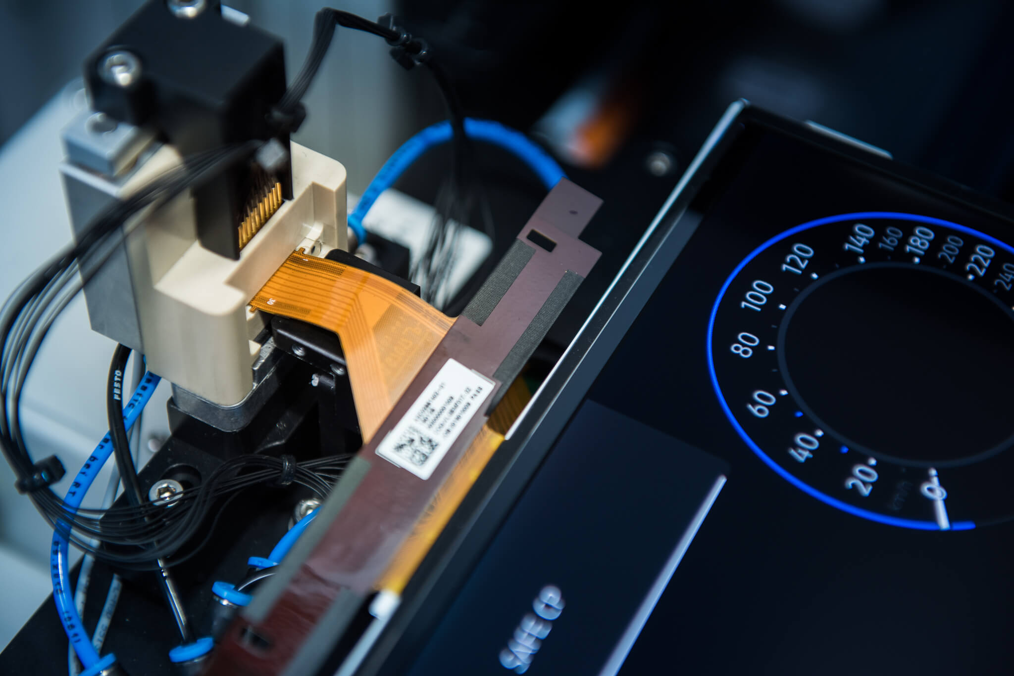
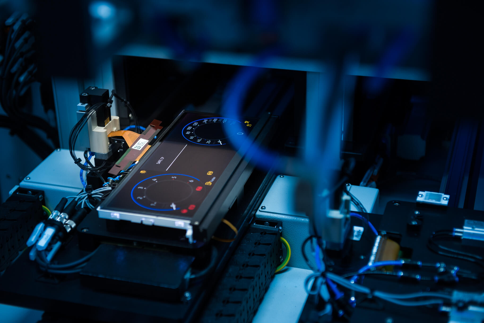
During the EOL functional test, a specially designed connector establishes a stable connection to the product, enabling both power supply and system communication. Once the product is powered up, a series of tests can be conducted to detect and rectify any potential defects. The solution supports a common variety of display tests such as touch tests, subpixel tests, homogeneity tests, particle detection, and similar.

The selection of test probes is critical to ensure a robust and reliable connection. Specialized probes with coaxial cables are used for high-frequency signals, reducing the risk of environmental interference.

7 End of line test

7.1 Product contacting

Contact us

Reach out for personalized service and expert guidance tailored to your unique needs. Our team is ready and eager to respond to any challenge.

Contact Form

Your personal data will be processed by INEA d.o.o., Stegne 11, Ljubljana, based on legitimate interest (communication with customers and the public, Article 6(1)(f) of GDPR) for the purpose of responding to your question or inquiry. We will only keep your personal data until the end of our communication. If you have given us consent (Article 6(1)(a) of GDPR) to receive personalized e-news and offers, we will process your personal data for the purpose of sending newsletters and offers until revoked. Predictions about your interests will be based on your inquiries regarding our solutions. You can unsubscribe from receiving emails at any time by clicking the unsubscribe link in the received message. For more details, please read our Privacy Policy.