Backlight Assembly

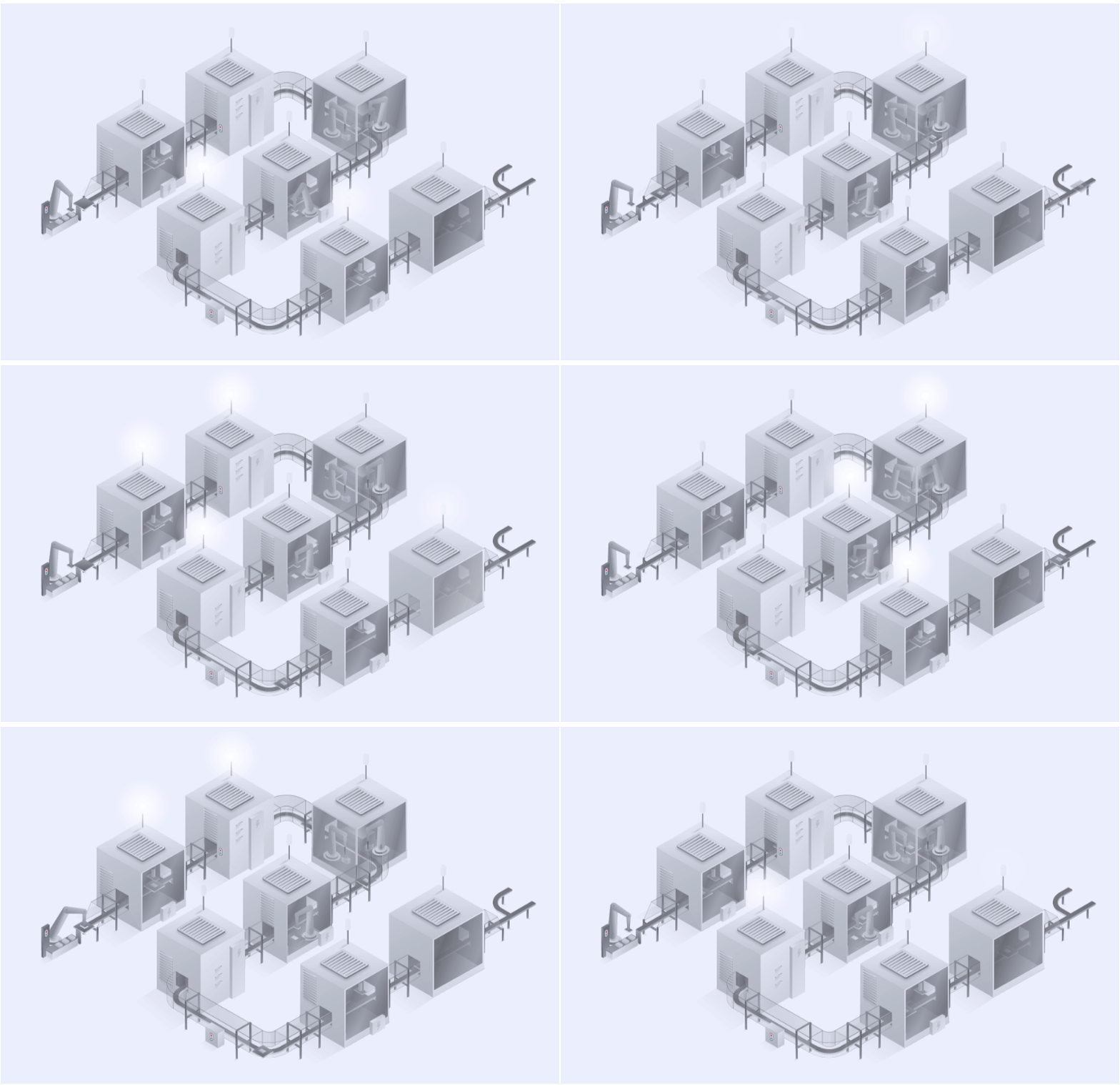
Completely automated assembly line and process optimization with energy saving capabilities and automatic feeding mechanism for long line autonomy. Assemble all layers of any shape of LCD backlight using custom tooling for precise application and quick changeover between products.

In-house developed special ISO 7 clean room emulation inside each assembly station significantly reduces costs of line installation. The lines are accessible for maintenance and loading but only require one operator control point for regular production due to a high level of MES integration and in-line quality control.

1
  • 1Diecast Loading
  • 1.1Tray Feeding Mechanism
  • 1.2Robot Pick & Place
2
  • 2LED PCB and diecast assembly
  • 2.1Thermal Tape Application
  • 2.2LED PCBA Press
3
  • 3Light guide assembly
  • 3.1Tray Feeding Mechanism
  • 3.2Robot Pick & Place
  • 3.3Placement Verification
4
  • 4Bumper assembly
  • 4.1Vibrating Feeding Mechanism
  • 4.2Robot pick and place
  • 4.3Placement verification
5
  • 5Optical foil assembly
  • 5.1Foil Feeding Mechanism
  • 5.2Robot pick and place
  • 5.3Placement verification
6
  • 6Light seal tape assembly
  • 6.1Tape Feeding Mechanism
  • 6.2Robot pick and place
  • 6.3Placement verification
7
  • 7Cover plate assembly
  • 7.1Tray feeding mechanism
  • 7.2Robot pick and place
  • 7.3Placement verification
  • 7.4Protection Foil Peel Off
  • 7.5Repress
8
  • 8Optical inspection
  • 8.1Product Contacting
Add-on

Functionality test

To ensure that only good parts are passed forward, various functionality tests are performed at the end of line. All test results and measurements are reported to the information system for 100%...

Add-on

End of line calibration

At end of line the products are calibrated to ensure the highest quality. The biggest challenge for the display calibration is white point calibration. This process requires specialized hardware and software, such...

Add-on

Manual test

If required, a manual test station can be positioned at the end of line. The product is contacted and powered up with specially designed images for the operator to determine any potential...

Add-on

Protection foil placement

After detailed product testing, protection foil for display and other critical cosmetic components is placed on the product to avoid any potential damage during the transportation and final product installation. The station...

1 Diecast loading

1.1 Tray Feeding Mechanism

Diecasts are usually packed in trays, which are loaded into the feeder manually or by AGVs. This feeder consists of an input conveyor, stack separator, single track transport system, tray stacker, and an output conveyor. The tray feeding mechanism is capable of handling trays up to 400mm in width and 600mm in length. To increase the autonomy of the assembly machine, the input and output conveyors of the tray feeding mechanism can be extended if space is available.

The stack separator and tray stacker form the core of the mechanism. They are custom-built and adapted to trays of various sizes and materials. Servo systems with special-purpose clamping mechanisms are employed to precisely separate these trays. A sophisticated vision system detects the position and orientation of the product, ensuring required product picking precision of less than 0.1 mm. Parts whose position and orientation can't be precisely distinguished on the feeding tray necessitate an additional pick and place mechanism on a backlit table.

Overall, the tray feeding mechanism is an efficient and reliable way to automate the feeding of various components to the assembly process, reducing the need for manual labor and improving production efficiency.
1 Diecast loading

1.1 Tray Feeding Mechanism

1 Diecast loading

1.2 Robot Pick & Place

Robots are used for a repeatable precision of up to 0.01mm for placement tasks. High-level accuracy is achieved using techniques such as bush guiding combined with robot torque control, force sensors, and stroke measurements. A “stack of tolerances” analysis is conducted to ensure assembly precision and an integrated vision system is used to accurately discern diecast orientation and position for handling purposes. High-level accuracy is achieved using techniques such as bush guiding combined with robot torque control, force sensors, and stroke measurements.

For product manipulation, robots are equipped with grippers featuring clamping fingers or vacuum cups. Special grippers can be mounted on either pneumatic cylinders for straightforward tasks or servo motors for more intricate ones. Servo driven grippers can handle a diverse range of objects due to their programmable gripping stroke and force. Force sensors are incorporated into the grippers to allow the robot to dynamically adjust its grip, ensuring the safety of delicate components. For particularly challenging product manipulations and complex assembly tasks, grippers augmented with additional sensors are utilized.

Overall, the entire pick-and-place process is typically automated and can be programmed to repeat the same operation over and over again, with minimal human intervention. This makes it a highly efficient and reliable manufacturing method with consistent quality and accuracy.

1 Diecast loading

1.2 Robot Pick & Place

2 LED PCB and diecast assembly

2.1 Thermal Tape Application

Thermal tape is used to bond the LED PCBA with the diecast housing. It provides a mechanical bond and thermal conductivity for heat dissipation. Thermal tape can be fed on a roll or from a manually-loaded stack. The LED PCBAs can be loaded on a stack, manually or by AGVs if a tray feeder is used.

An advanced vision system detects the position of the LED PCBA and thermal tape prior to the robot pick. The robot picks up the LED PCBA with a vacuum gripper and places it into a custom-made nest. The robot then picks the thermal tape and peels off the protection foil. In the case of thermal tape feeding from a roll, robot can skip the protection foil peel off operation.

2 LED PCB and diecast assembly

2.1 Thermal Tape Application

2 LED PCB and diecast assembly

2.2 LED PCBA Press

The phase consists of two operations: robot assembly and repress. A robot picks the sub-assembly (LED PCBA and thermal tape) and peels off the second thermal tape protection foil. The robot assembles the sub-assembly and diecast with a sophisticated, precisely calibrated move.

To activate the adhesive properties on the thermal tape, it has to be pressed for a specific time under a specific force by high precision servo press or robot with force measurement. The key to good adhesive activation is the distribution of press force over the complete glue area. For this purpose, special air dampers are used to distribute the force evenly over the entire LED PCBA. For quality assurance, the parameters (force and time) are recorded, compared with nominal values, and reported into the information system for each individual product.

2 LED PCB and diecast assembly

2.2 LED PCBA Press

3 Light guide assembly

3.1 Tray Feeding Mechanism

Due to their fragility and sensitivity, light guides are delivered in trays that are custom-designed for this purpose. To manage such specialized trays, a tray feeding mechanism is used, which is composed of an input conveyor, a stack separator, a single-track transport system, a tray stacking mechanism, and an output conveyor. This mechanism has the capability to handle trays measuring up to 400mm in width and 600mm in length. If spatial constraints permit, the input and output conveyors can be extended to enhance the assembly machine's operational autonomy.

Central to the mechanism are the stack separator and the tray stacking unit. These elements are engineered to be adaptable to trays made from various materials and of different sizes. To achieve exact tray separation, servo systems equipped with specialised clamping mechanisms are used. A vision system is implemented to accurately determine the product's orientation and position for a picking precision of less than 0.1 mm. In instances where the feeding tray does not allow for precise identification of a component's position and orientation, an additional pick-and-place mechanism is needed, which operates on a backlit table.

Overall, the tray feeding mechanism is an efficient and reliable way to automate the feeding of various components to the assembly process, reducing the need for manual labor and improving production efficiency.

3 Light guide assembly

3.1 Tray Feeding Mechanism

3 Light guide assembly

3.2 Robot Pick & Place

A robot does the automatic assembly of the light guide. It uses a vision system to accurately determine the orientation and position of parts. Before designing the robot's functionality, a “stack of tolerances” analysis is conducted to assess assembly precision. Various strategies ensure high-precision assembly, such as bush guiding with robot torque control, force sensors, and stroke measurement. The robot uses a custom-built gripper that incorporates diverse gripping technologies:
o For light guide assembly, a flat or curved vacuum gripper is employed, depending on the final product. This gripper has a special polyurethane foam that is rigid for precise product positioning but soft enough to avoid damaging the delicate light guide essential for high-quality display backlighting.

o Grippers specifically designed for complex tasks are equipped with various sensors, like force and torque. When assembling light guides, the robot must angle the product and press it against the die-cast wall for successful assembly. A force sensor measures the force applied to ensure no damage occurs during assembly.
Overall, the entire pick-and-place process is typically automated and can be programmed to repeat the same operation over and over again, with minimal human intervention. This makes it a highly efficient and reliable manufacturing method with consistent quality and accuracy.

3 Light guide assembly

3.2 Robot Pick & Place

3 Light guide assembly

3.3 Placement Verification

Early detection of defective components reduces scrap, material consumption, and costs; increasing productivity. A vision system is used to verify the presence and accurately measure the position and orientation of the components, achieving a required precision of less than 0,1mm.

Various measurement parameters are linked with product ID, cross-checked with nominal values, and reported to the information system. If the measured values are outside the set tolerances, the system proceeds in one of two ways:

 Fully Automatic Mode: The part is marked as NOK, and is not processed further. This mode requires no operator intervention. At the end of the line, the components on the carrier are unloaded, analysed and scraped or sent for a rework. This mode requires no operator intervention.

 Manual Mode: An alarm is triggered for operator intervention. The operator then assesses whether the components are suitable for continuation. If the operator assesses the results as unsuitable, they manually remove the part and resets the system for the robot to load new components.

3 Light guide assembly

3.3 Placement Verification

4 Bumper assembly

4.1 Vibrating Feeding Mechanism

Flexible vibrating feeding mechanisms are used for material packed in bulk. The core of the system is a backlit vibrating plate, which has a vibrating hopper for material feed, and an advanced vision system for material position and orientation detection. Autonomy is defined by the size of the hopper where the bulk material is fed.

The feeder offers high performance part feeding, preorientation, and optimal surface distribution of bulk parts. It is compatible with most shapes including complex geometries and delicate materials. Due to multiple axis vibration, parts can be moved in all directions, including the optimal flipping amplitude for each type of component. An intelligent vision system detects and checks the position and orientation of each component on the vibrating plate. That information is then fed to the robot, which picks up correctly oriented parts. The vibrating plate is then activated again to orient more parts correctly.

4 Bumper assembly

4.1 Vibrating Feeding Mechanism

4 Bumper assembly

4.2 Robot pick and place

A robot using a custom gripper with an ejecting needle assembles bumpers. The robot selects a bumper from a vibrating feeder with a help of camera-guided positioning. For precise assembly, the robot mimics a human-like movement, inserting the bumper at an angle into a slot. Once inserted, the needle retracts.

Overall, the entire pick-and-place process is typically automated and can be programmed to repeat the same operation over and over again, with minimal human intervention. This makes it a highly efficient and reliable manufacturing method with consistent quality and accuracy.

4 Bumper assembly

4.2 Robot pick and place

4 Bumper assembly

4.3 Placement verification

A special measurement mechanism verifies bumper height. It checks if the bumper's height is within a set value to prevent further assembly issues. A vision system is used to verify the presence and accurately measure the position and orientation of the components.

Measurement parameters are linked with product ID, cross-checked with nominal values, and reported to the information system. If the measured values are outside the set tolerances, the system proceeds in one of two ways:

▪ Fully Automatic Mode: The part is marked as NOK, and is not processed further. This mode requires no operator intervention.At the end of the line, the components on the carrier are unloaded, analysed, and scrapped; or sent for a rework. This mode requires no operator intervention.

▪ Manual Mode: An alarm is triggered for operator intervention. The operator then assesses whether the components are suitable for continuation. If the operator assesses the results as unsuitable, they manually remove the part and resets the system for the robot to load new components.

4 Bumper assembly

4.3 Placement verification

5 Optical foil assembly

5.1 Foil Feeding Mechanism

The foil feed mechanism begins with a foil stack that can hold up to 1,000 foils per stack or more if multiple stacks are used. The mechanism employs a pick-and-place system as well as an intelligent vision system that can detect foil shape, position, and orientation. The autonomy is defined with the size and number of input stacks. This separation process utilizes moving vacuum cups and ionized air, delivered via specially shaped nozzles, to ensure individual foil separation. Variants of this mechanism can cater to specific needs, such as Z-fold packaging.

At the core of the foil feed is a system with both top and bottom protection foil peel-off capabilities. It employs an industrial single-side adhesive tape, driven by two torque-controlled servo drives set up in a master-slave configuration. This setup maintains consistent tape tension for optimal performance. The tape's speed is kept uniform between the top and bottom peel-off systems through servo gearing. Additionally, to counteract speed differences due to varying tape diameters, the tape roll's diameter is monitored. For consistent and smooth peeling, the mechanism is fitted with specialized peel-off knives. For parts not distinctly recognizable on the foil feed mechanism, an additional pick-and-place system combined with a backlit table can be added to enhance clarity.

5 Optical foil assembly

5.1 Foil Feeding Mechanism

5 Optical foil assembly

5.2 Robot pick and place

For high-quality display backlight, foils like BEF, D-BEF, and LCF are used. These foils are handled using a flat or curved vacuum gripper (depending on the final product) equipped with special polyurethane foam. This foam is rigid enough for precise positioning yet gentle to prevent damage to the sensitive foils. Foils are placed on a pick table where a camera checks their position and relays it to the robot. The robot then uses the gripper, which has a sectional vacuum system, to ensure reliable picking.

Overall, the entire pick-and-place process is typically automated and can be programmed to repeat the same operation over and over again, with minimal human intervention. This makes it a highly efficient and reliable manufacturing method with consistent quality and accuracy.

5 Optical foil assembly

5.2 Robot pick and place

5 Optical foil assembly

5.3 Placement verification

Early detection of defective components reduces scrap, material consumption, and costs; increasing productivity. Foil thickness is measured using a special digital contact measurement sensor with the precision of 0,001mm.

Measurement parameters are linked with product ID, cross-checked with nominal values, and reported to the information system. If the measured values are outside the set tolerances, the system proceeds in one of two ways:

▪ Fully Automatic Mode: The part is marked as NOK, and is not processed further. This mode requires no operator intervention.At the end of the line, the components on the carrier are unloaded, analysed, and scrapped; or sent for a rework. This mode requires no operator intervention.

▪ Manual Mode: An alarm is triggered for operator intervention. The operator then assesses whether the components are suitable for continuation. If the operator assesses the results as unsuitable, they manually remove the part and resets the system for the robot to load new components.

5 Optical foil assembly

5.3 Placement verification

6 Light seal tape assembly

6.1 Tape Feeding Mechanism

The light seal feeding mechanism is used when the input material is provided in tape reels. This system is composed of a servo feeding mechanism, a peel-off knife, and a vision system. The liner tape is fed by two torque-controlled servo drives, operating on a master-slave configuration. This setup ensures consistent liner tape tension, vital for maintaining quality. To coordinate the liner tape movement with the robot's actions, a rotary encoder feeds necessary data on speed and position to the robot.

For light seal placement with high precision of less than 0.1mm, an advanced vision system identifies both the position and orientation of the light seal on the liner tape. To enhance the reliability of the process, a specialized nozzle releases ionized air right below the peel-off knife, ensuring smooth detachment. The servo liner tape feeder and robot work in tandem, carefully peeling off each item from the liner tape. The design of the peel-off knife is tailored to the product's shape, liner tape material, and adhesive strength.

6 Light seal tape assembly

6.1 Tape Feeding Mechanism

6 Light seal tape assembly

6.2 Robot pick and place

In the light seal placement process, a robot guided by a vision system places tape around critical parts of the display panel. This tape acts as a light-tight barrier, preventing unwanted light leakage between different layers of the display. The robot picks the light seal tape, positions it accurately, and presses to ensure firm adhesion. Subsequent quality control checks validate the tape's positioning and adherence, guaranteeing the display panel's desired quality and performance.

Overall, the entire pick-and-place process is typically automated and can be programmed to repeat the same operation over and over again, with minimal human intervention. This makes it a highly efficient and reliable manufacturing method with consistent quality and accuracy.

6 Light seal tape assembly

6.2 Robot pick and place

6 Light seal tape assembly

6.3 Placement verification

Vision control of the light seal provides real-time visual feedback of the tape positioning. It inspects the tape's alignment along display edges, ensuring it properly covers inter-layer gaps and sticks without any misalignments or creases. Any deviations or defects can be immediately detected. The light seal tape thus effectively prevents light leakage, maintains display quality, and meets stringent quality control standards set by the manufacturer.

Measurement parameters are linked with product ID, cross-checked with nominal values, and reported to the information system. If the measured values are outside the set tolerances, the system proceeds in one of two ways:

▪ Fully Automatic Mode: The part is marked as NOK, and is not processed further. This mode requires no operator intervention.At the end of the line, the components on the carrier are unloaded, analysed, and scrapped; or sent for a rework. This mode requires no operator intervention.

▪ Manual Mode: An alarm is triggered for operator intervention. The operator then assesses whether the components are suitable for continuation. If the operator assesses the results as unsuitable, they manually remove the part and resets the system for the robot to load new components.

6 Light seal tape assembly

6.3 Placement verification

7 Cover plate assembly

7.1 Tray feeding mechanism

Cover plates are typically housed in trays, either loaded manually or via Automated Guided Vehicles (AGVs) into the tray feeding mechanism. It is made of an input conveyor, a stack separator, a single-track transport system, a tray stacking mechanism, and an output conveyor. This system is engineered to accommodate trays with dimensions up to 400mm in width and 600mm in length. Given enough space the assembly machine's operational autonomy can be increased by extending both the input and output conveyors.

The stack separator and the tray stacking unit form the core of the mechanism. These components are specifically engineered to be compatible with trays of diverse sizes and material compositions. Specialized servo systems, equipped with clamping mechanisms designed for this purpose, are utilized for the accurate separation of trays. An advanced vision system is deployed to identify the spatial orientation and position of the product, thereby achieving a product picking accuracy finer than 0.1 mm. When the feeding tray's limitations prevent precise identification of a part's position and orientation, an auxiliary pick-and-place system is required, functioning on a backlit table.

Overall, the tray feeding mechanism is an efficient and reliable way to automate the feeding of various components to the assembly process, reducing the need for manual labor and improving production efficiency.

7 Cover plate assembly

7.1 Tray feeding mechanism

7 Cover plate assembly

7.2 Robot pick and place

Using a backlit table, cover plates are positioned for robot interaction. A camera determines the plates' exact position and angle, and sends this data to the robot. The robot, equipped with a gripper, flat or precisely curved to match the product, picks up the cover plate and peels off its protective foil. To ensure accuracy in placement, the camera checks the product's alignment in the carrier nest, providing placement guidance to the robot. It then places the cover plate and gently presses against the housing to ensure cover plate fixation before the repress station.

Overall, the entire pick-and-place process is typically automated and can be programmed to repeat the same operation over and over again, with minimal human intervention. This makes it a highly efficient and reliable manufacturing method with consistent quality and accuracy.

7 Cover plate assembly

7.2 Robot pick and place

7 Cover plate assembly

7.3 Placement verification

Early detection of defective components reduces scrap, material consumption, and costs; increasing productivity. A vision system is used to verify the presence and accurately measure the position and orientation of the cover plate.

Various measurement parameters are linked with product ID, cross-checked with nominal values, and reported to the information system. If the measured values are outside the set tolerances, the system proceeds in one of two ways:

▪ Fully Automatic Mode: The part is marked as NOK, and is not processed furter. This mode requires no operator intervention. At the end of the line, the components on the carrier are unloaded, analysed and scraped or sent for a rework. This mode requires no operator intervention.

▪ Manual Mode: An alarm is triggered for operator intervention. The operator then assesses whether the components are suitable for continuation. If the operator assesses the results as unsuitable, they manually remove the part and resets the system for the robot to load new components.

7 Cover plate assembly

7.3 Placement verification

7 Cover plate assembly

7.4 Protection Foil Peel Off

The protection peel off mechanism is used to peel off various protection foils from components. This system is comprised of a 6-axis robot, a peel-off knife, and two master-slave torque-controlled servo motors utilized for winding adhesive tape. They ensure consistent tension and controlled winding of the adhesive tape, preventing damage and ensuring efficient operation. The movement of the robot is specifically tailored to the product for a reliable peel-off process. An external encoder is integral to the system, synchronizing the movement of the adhesive tape with the robot.

7 Cover plate assembly

7.4 Protection Foil Peel Off

7 Cover plate assembly

7.5 Repress

The repress operation is a process used to activate the adhesion of components through the application of force. Used in this case to adhere the components of the cover plate, this operation relies on a rigid C-frame, designed specifically to counterbalance the force needed to activate the adhesive. Depending on the application and requirements, various pressing methods are available. The electrical servo press, for instance, can achieve higher forces with greater precision, with its force regulated by servo torque.

Alternatively, if extreme precision isn't crucial and cost-effectiveness is a priority, pneumatic press systems can be used instead. These systems regulate force through pressure adjustments.

7 Cover plate assembly

7.5 Repress

8 Optical inspection

8.1 Product Contacting

To power up the backlight, a special connector with precise servo driven axis is used. This is especially importat if the “stack of tolerances” exceeds the pitch of a ZIF or LIF (zero- or low-insertion-force) connector. This mismatch can create issues when trying to power up the backlight.

To overcome this, the vision system determines the exact position of contacting surfaces on the connector. Precise servo mechanism adjusts the contacting head position before contacting. The system is designed to handle a contact pitch as fine as 0.5mm and can accommodate other types of connectors.

Once aligned and contacted, two important tests of the backlight are performed. A homogeneity test detects any uneven lighting of the backlight, while a particle detection test ensures that the backlight module is without any debris that coud distort the quality of the end product.

8 Optical inspection

8.1 Product Contacting

Contact us

Reach out for personalized service and expert guidance tailored to your unique needs. Our team is ready and eager to respond to any challenge.

Contact Form

Your personal data will be processed by INEA d.o.o., Stegne 11, Ljubljana, based on legitimate interest (communication with customers and the public, Article 6(1)(f) of GDPR) for the purpose of responding to your question or inquiry. We will only keep your personal data until the end of our communication. If you have given us consent (Article 6(1)(a) of GDPR) to receive personalized e-news and offers, we will process your personal data for the purpose of sending newsletters and offers until revoked. Predictions about your interests will be based on your inquiries regarding our solutions. You can unsubscribe from receiving emails at any time by clicking the unsubscribe link in the received message. For more details, please read our Privacy Policy.